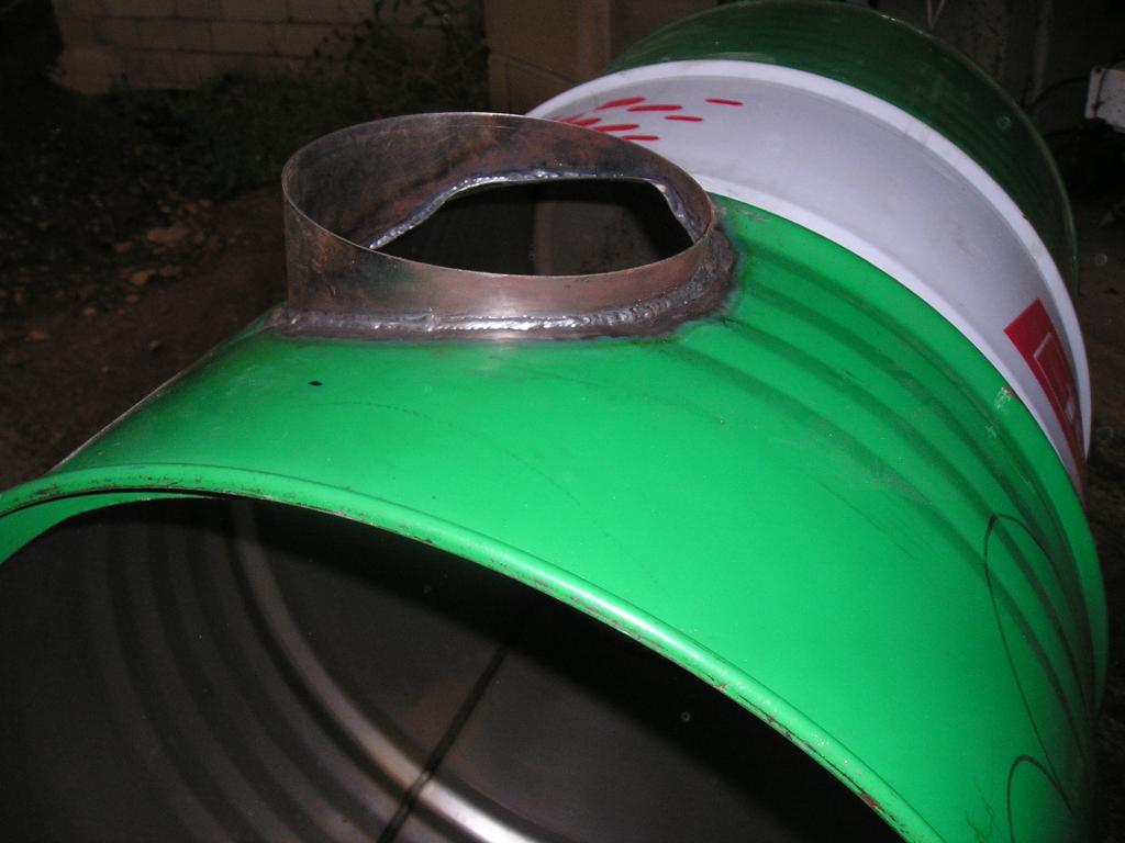
Glory hole constructed using a 45 UK gallon (205 litre) oil drum. The top was cut out using an air nibbler and then thoroughly washed to remove oil residue. Approximately 16mm of the drum top was retained to act as a retainer for the heat retention ring when that was cast in place.
Burner port cowl welded in place. This was provided to
add support to the castable burner port. The glory hole was drawn in
front elevation in a CAD package and the flat shape of the cowl drawn
then printed on 3 sheets of A4 sized paper. These were stuck to the
steel sheet and the shape cut out. The cowl was then formed into a ring
and welded. I didn't bother to include the swagings in the drawing but
instead cut the cowl to fit the swages at this point. Prior to welding
the cowl to the drum the hole was marked and cut out leaving about 5mm
inside the cowl to act as a positive register for the castable.

The burner port core constructed from 4 pieces of 90mm
square wood because thats what I had. This was glued together and once
dry the ends carefully turned down to take steel rings. The steel rings
at both ends were added for peace of mind when the main tapers were turned
at about 800RPM. The core is about 116mm at the small end of the shallow
taper on the left, this diameter is intended to take a Gibberson burner
head or similar.This taper is about 4° included angle to allow
for removal. The main taper is 24° included angle from details
given at www.joppaglass.com . As shown here it has been sanded to achieve
a fine finish. This was then given 3 coats of cellulose laquer. When used
it was given a light coating of Vaseline to aid removal.

Burner port core support structure strapped in place.
The 4 screws evident between the straps hold the core to a piece of 6mm ply.
This ply is held to the thicker ply using 4 more screws further out from
the centre and spaced using washers to achieve the desired position. The
original intention was to allow for angular adjustment but in the end all
4 stacks of washers were the same. The thicker ply consists of a 6mm piece
underneath to locate around the cowl and an 18mm piece to form the outer
face of the burner port. The burner port core passes through the 18mm ply.
Not in this picture but added later was a 3mm steel plate under the 4 screws
holding the core the the 6mm ply. This was a striking plate for a needle
scaler used to vibrate the core to aid compaction of the castable.
Frontal view giving an indication of the tangential nature of the burner port entry.
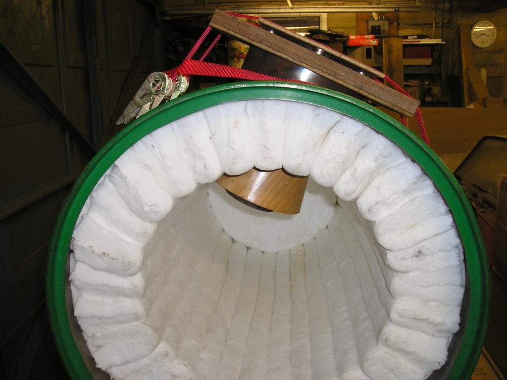
The fibre was added based on instructions given in Glassnotes
by Harry Halem. The fibre was inserted having been wetted. Towards the
end of the procedure 2 pieces of aluminium sheet were placed between the
fibre folds to aid entry of the new fibre fold. Suprisingly once the insertion
of the new section was started the aluminium was removed as the fibre didn't
catch readily on the adjascent folds and could be manipulated easily
with a vinyl gloved hand. I stopped adding folds when it became too difficult
to add more. Shown here comprising the folds is an entire 7.32m roll of 1400°C
25mm 128kg/m³ (8lb/ft³) fibre. The back is 3 layers of 1260°C 25mm 128kg/m³
(8lb/ft³) fibre. Remaining backing discs in 1400°C fibre were added later
to bring the glory hole depth to about 635mm (25")

The space to be filled with castable. The fibre was cut
using a disposable multi-segment utility knife at full extension. Blade
could be thrown away after use as the fibre is very abrasive and kills
the edge quickly.

The castable was added in stages and at each stage the needle scaler was applied to the under side. Use of vibration transforms the nature of the castable and causes it to flow out far more readily than if it was just packed from above. This helps to expel air and aids its filling of the void to create a fully dense castable. Once the lowest point was reached though manual packing was done as otherwise the castable would flow out over the fibre.
Prior to use I would suggest trying a sample of the castable
intended for use. The supplier should be able to provide water mix ratios
for use. Adding too much water can cause excessive separation of the components
of the castable and lead to a weak result.
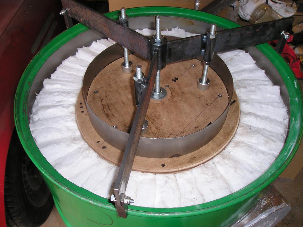
Barrel set-up and levelled with heat rentention ring former in place. This assembly allows the inner ring to be positioned level with the front face of the drum. Approximately 28kg of castable was added in 3 stages. At each stage a wooden block was placed on the castable and the needle scaler applied to the top. This was worked over the entire surface and caused the castable to flow out level and fill the void.
The numbering evident is to allow for correct assembly
of the former. The steel ring is held by 3 tabs between a single piece
upper disk and a 4 piece lower disk. The 4 piece lower disk allows for
removal once the heat retention ring has been cast.
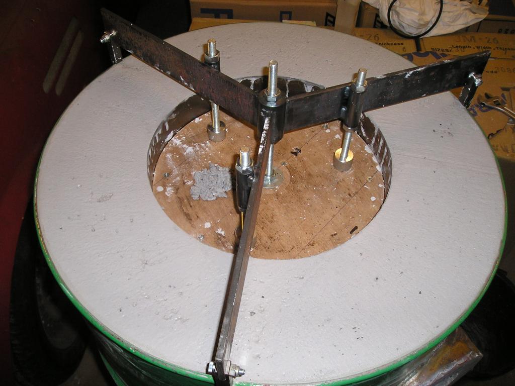
At the last stage a piece of 50mm
x 6mm steel bar was used to bridge between the outer drum face and the
inner ring. The needle scaler was then applied to this and allowed the surface
to be levelled flush giving the result shown here. After leaving to set
for a day the central disc was removed and the steel work removed allowing
the lower 4 parts to be removed. The inner steel ring was unfortunately destroyed
during removal so next time I may not weld the join but leave it just butted.
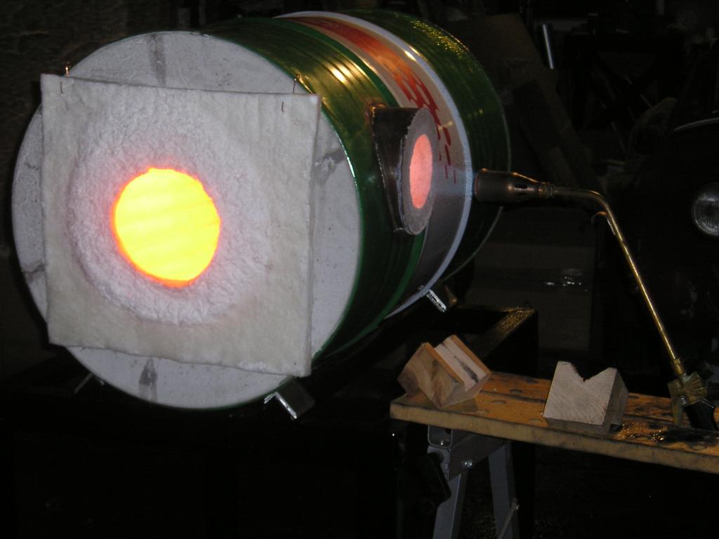
No doors constructed yet and no burner assembly so a test with a Sievert torch and a temporary fibre door. This is a Sievert 2944 burner head running with just the pilot burner on the torch turned up full at 2 bar pressure. This would seem to reach the temperature required judging from the colour. The main problem which will be solved with a multi-hole burner is the noise of a single flame burner of this size.
I wish I had an anti-gravity glory hole stand but its actually
just dark out and I painted it black.